PIC18F2550 KS0108 Graphical LCD Oscilloscope

Using the PIC18F2550 GLCD Text Test as a basis for further experimentation, I put together a simple and accurate graphical oscilloscope using a PIC18F2550 microcontroller and a AGM1264F graphical LCD. The oscilloscope measures the average voltage, the maximum voltage, the minimum voltage, the peak-to-peak voltage, and the zero-crossing frequency for a DC signal over 100 samples. The oscilloscope has a built in edge trigger function that can be set to capture on rise or fall (or disabled altogether). The time scale for the display is variable and can be easily redefined using the changeTimeDivision function. Likewise, the voltage range can be change to 0-5V, 0-2.5V, and 0-1.25V. The main limitations of this oscilloscope include relatively slow acquisition time and sampling rate (~60kHz) and the fact that the inputs are limited by the constraints of the internal ADC. However, it is a very nice display and I highly suggest you view the videos to see it in action.

Full Circuit

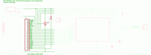
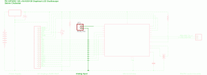
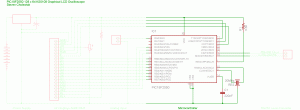
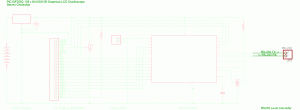
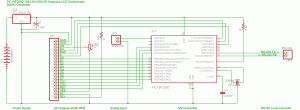
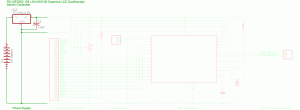
The source and firmware for the circuit can be found at the bottom of the page. Each section of the circuit is labeled in the schematic. All of the sections and their components are described and discussed below. The part numbers for the components are linked to websites for data and more information when available.

Power Supply

The power supply uses a 9 volt battery and a TC1262-5.0V high-accuracy low-dropout linear voltage regulator to provide a stable 5 volt supply for the microcontroller and the graphical LCD. A 1uF (microFarad) polarized decoupling capacitor is necessary on the output of the voltage regulator to prevent power spikes or ripples. A wall wart power supply as low as 5.3V can be substituted for the 9 Volt battery.

AZ Displays AGM1264F

The AGM1264F is 128 x 64 pixel graphical LCD with built in controllers that allow is to be easily controlled using a PIC microcontroller. It is a 128 x 64 pixel graphical LCD and has an LED backlight, onboard negative voltage generator (LMC7660) for LCD driving, onboard Samsung KS0108 controller, and an 8-Bit MPU interface.

Analog Input

The 1st analog input (Pin A0) is configured to be an analog input. Please note that “The source impedance affects the offset voltage at the analog input (due to pin leakage current). The maximum recommended impedance for analog sources is 2.5 kΩ.” (PIC18F2550, p.260)

Microcontroller

The microcontroller used is a Microchip PIC18F2550. I modified the PIC18F2550 Tiny PIC Bootloader assembly file so I could use a 20MHz crystal/resonator at 115,200 baud (the modified bootloader can be found at the bottom of the page). The PIC18F2550 runs at 48MHz using the internal PLL. R1 is a pull-up resistor necessary for operation. C1 is a stabilizing capacitor that is used for the onboard USB voltage regulator, which is not used in this project. The component marked ‘RES’ is a 20MHz resonator.

RS232 Level Converter

The microcontroller USART pins need to be connected to a RS-232 Level Converter to connect to a PC for firmware updates using the Tiny PIC Bootloader. Otherwise, after initial programming they can be left disconnected.

Source and Firmware
The PIC must initially programmed with the ‘SAC_tinybld18F2550usb _20MHz_115200_48MHz’ hex file to program the bootloader on the PIC. Then, using Tiny PIC Bootloader, the hex file can be placed on the chip using the Tiny PIC Bootloader frontend with ’12h 34h 56h 78h 90h’ in the ‘List of codes to send first:’ in the ‘Options’ menu. Please feel free to contact me if you have any problems.

Videos
Here are three videos of the PIC18F2550 GLCD Oscilloscope in action. The first video demonstrates sine, triangle, and square waves of different frequencies. The second video demonstrates different waves with shifting amplitudes and offsets. The third video compares the display of the PIC18F2550 GLCD Oscilloscope to the display of a Hewlett Packard 54603B oscilloscope.

Update (November 15, 2006)
Here is the firmware without the bootloader code:

Update (February 1, 2007)
Here is untested firmware for the PIC18F4550 without the bootloader code:

Update (April 11, 2007)
Here is untested firmware for the PIC18F252 and PIC18F452 without the bootloader code. Please note that you will need to use a 10MHz crystal/resonator instead of a 20MHz one.
167 thoughts to “PIC18F2550 KS0108 Graphical LCD Oscilloscope”

  1. Guntis – Yes, you can use a PIC18F4550. The architecture is the same, as is the memory mapping. All that you need to do is double check the pin definitions and change the device include at the top of the source code to: #include <18F4550.h> before you recompile.

  2. It’s don’t work on my GLCD: type: tech12864g
    see the pins of LCD:
    ———————–
    1-vss
    2-vdd
    3-v0
    4-rs
    5-r/w
    6-e
    7-b0
    8-b1
    9-b2
    10-b3
    11-b4
    12-b5
    13-b6
    14-b7
    15-cs1
    16-rst
    17-vee
    18-cs2
    19-backlight
    20-backlight

    ——————————————————

  3. Luis – I checked a datasheet for the TECH12864G and noticed that the display may not have a negative voltage generator for VEE and VO. The LCD should work with this schematic (other than the different pinout) because the controller is the same. Can you check to see if the output of VEE is about -10V?

  4. Nice work ! Did you plan to use an external A/D converter ? a serial one, maybe… How about Logic Analizer ?

  5. Hi,
    with the firmware without bootloader (Update 15 Nov 2006), I program the pic and it works? Nothing else? Great project!!!

  6. Nicu – An external A/D converter would help increase the sampling rate. Right now the oscilloscope acts as a storage oscilloscope. I could greatly increase the speed and resolution of the oscilloscope if I used an external ADC. As for using it as a logic analyzer, to be honest I hadn’t considered it. A logic analyzer would be very easy to put together with a PIC. The only issue that I could think of is whether or not the resolution of the LCD (128×64) is high enough for multiple channels.

    Mimmo – For the firmware without bootloader, yep, all you need to do is program the PIC, make the necessary connections, and it will work! Please note that this version of the firmware has a set resolution and update rate. I plan on building an oscilloscope with a rotary encoder and pushbutton to change settings.

  7. Thanks Steve,
    I cannot understand C, only assembler and PicBasiPro, so I am not able to modify your C firm to manage pushbuttons or a rotary encoder. I will wait your next relase, hi. I have all materials, so I can start to build it.
    It would be nice to use an external A/D converter to increase performaces from a simple “logic analyzer” to a nice “oscilloscope” even if with only one channel. Congrats again.
    Ciao from Rome – Italy

  8. How about using Microchip USB bootloader ? I think that 128×64 pixels should be ok for Logic Analizer… or a bigger one could be used 😀

  9. I also think it owuld be very nice to have the code available in BASIC or pseudo code. This way it could easily be ported to other uC’s. I am more of an AVR guy :p Maybe even just a flow chart of the process? If you ever do, it’d be nice if you let me know! I’d really be interested!

  10. Matthieu – I haven’t ported the code to BASIC or pseudo code, but that is definitely a future possibility! The CCS C code should be ANSI C (although it includes a number of functions that are internally defined), so it should be possible to port it to an AVR (using avr-gcc). I’ll keep updating and see what I can do!

  11. Steve, for work with slow indicators, such as XIAMEN GDH12864A and similar, in standard functions of recording and reading in LCD () is necessary to add file GLCD.C a delay on 2 uS between distribution of the data and signal E (pin 6 LCD/RC2) and also to increase on 2 uS duration of it строба. Otherwise the screen “collapses”. 😉
    Yours faithfully, Andrey. Moscow.

  12. Andrey – Some displays are slower than others, so yes, it would be beneficial to use the delay. On my display (AGM1264F) the screen updates perfectly fine without it; however, that does not mean that every KS0108 graphical LCD will. I have found that some HD44780 compatible drivers (text LCD drivers) have similar issues with signal processing speed, so you need to insert delays to ensure that there is no display corruption.

  13. Steve, Are you working on the new version of this little jewel? I’ve read you are planning to make an oscilloscope with buttons and rotary encoder to change setting. Do you think I can start to build this one and then update it with new firmware and wiring modifications as it will be available?
    Are there any issue on 18f2550 programming? Will a standard JDM programmer work with this pic?
    Thanks
    Francesco

  14. Francesco – Yes I am, but very slowly. I have been trying to complete human subject testing for one of my co-workers and it has taken much more time than either of us expected. It has been a long week (and weekend!). My planned updates include:

    1. Auto-ranging (both voltage and time domain)
    2. 3 pushbutton for manually changing parameters
    3. USB support, or at the very least USB bootloading

    If you can program the firmware initially then there should not be a problem in the future. Also, as long as the JDM programmer supports the PIC18F series (and specifically the PIC18F2550), then there will not be a problem. I checked online and found a couple of sites that say they support both the JDM programmer and the PIC18F2550 (http://www.members.aon.at/electronics/pic/picpgm/index.html, http://www.qsl.net/dl4yhf/winpicpr.html) though it seems like you might need to slightly modify the programming circuit.

  15. Please, can someone ported the originally code to “MikroC” or “MikroBasic” from Mikroelektronica?
    Thanks
    Vincenzo

  16. Vincenzo – I have not programmed using MikroC or MikroBasic, so unfortunately I can not easily port the progams. However, if MikroC is an ANSI C compiler, then porting the program from CCS C should not be too difficult.

  17. Hi Steve, Great job with this! I have a CREATE USB Interface with the PIC18F4550 and a LCD, but don’t have the CCS compiler… could you post a ‘4550 hex file (no bootloader) for me?

    Thanks
    -Dan

  18. #22 (Dan) – I am more than happy to provide a copy of the code and compiled hex for the PIC18F4550. One question I have though is if the CREATE USB interface requires firmware compiled to include ORG information for the USB bootloader. If not, then hopefully this will work without a problem. Please let me know!

  19. Hi Steve – Thanks! I’m using an ICD2 to program the CUI, so I’ll just overwrite the bootloader for now (can always put it back on)… Normally though, the USB bootloader resides in 0x0000,0x0800.

    Thanks again for the compliled hex – it’s too bad the CCS compiler demo doesn’t work on the PIC18F series, maybe I’ll have ot buy it some day…

    Cheers,
    -Dan

  20. Hi Steven,
    Your project looks great!! I love interesting projects like this. I emailed you a message about possibly extending this project for a senior design project. I would like your permission to perform something of that capacity. Please email me your decision.

    A prompt response will be greatly appreciated.

    P.S. My email address is in your inbox I asked you a question from http://www.semifluid.com.

    Thanks!

  21. Steve – Please check your mail. By the way I want to know the value of R3 used in circuit. And, for the using tiny bootloader, how can I erase the program code only without erase the bootloader code. Is the tiny bootloader erase and program the program code automatically after press “Flash”.

  22. #25 (Will) – Sorry for the delay in my response, I emailed and let you know that you are more than welcome to use my projects. All of my projects are licensed under the Creative Commons Attribution-Share Alike 2.5 License
    (http://creativecommons.org/licenses/by-sa/2.5/), although I don’t clearly state it on my webpage (maybe I should add that to the footer…). All that I ask is that you include me in your credits and publish the project in a similar manner.

    #26 (Ricky) – I’m catching up with emails right now. The value of R3 was intentionally left blank because it will be dependent upon your backlight. You can either use a potentiometer or a fixed resistor to set the brightness of your backlight. Check the datasheet for your LCD and you can choose an appropriate resistor given the current draw and voltage drop of the LEDs. Tiny PIC Bootloader automatically erases the necessary program space and programs it. You do not need to worry about overwriting or erasing the bootloader because the PC frontend makes sure to check the HEX for any incompatibility (and it will tell you if there is a problem with the memory space!).

  23. Steve – Long time no see, how are you?

    Finally, I got the ICD2 and program the “SAC_tinybld18F2550usb_20MHz_115200_48MHz.HEX ” on my PIC.

    However, when I use Tiny bootloader from http://www.etc.ugal.ro/cchiculita/software/picbootloader.htm, I can’t upload the program to my PIC.

    I did the following procedures:

    1) Connected the circuit as file per attached
    2) Set PC COM1 Config: 115200, 8 bits, Hardware control:Hardware, use FIFO buffer
    3) Executed Tiny bootloader
    4) Connected COM1 with circuit per attached
    5) Entered ’12h34h56h78h90h’ in the ‘List of codes to send first:’
    6) Press “writeflash”, and press switch on circuit as quick as possbile

    After taht the following message displayed:

    Connect COM1: ok
    Wait 100ms
    HEX: 35 days old, INHX32, 18F code+cfg, total=15548bytes
    Searching for PIC …Not found,
    ERRROR!

    And, sometime tiny bootloader can identified my PIC is PIC18F2550, but it will display “can’t write”.

    Would you please help to check is that any wrong in my circuit per attached, or any other solution on it? can I use ICD2 to program on the IC directly?

    The following link is the circuit:
    http://rickylab.tripod.com/tinubootloadercircuit001.jpg

  24. Hi everbody,
    I prepared a PCB for this osciloscope and I soldered the component on the PCB. When I powered on(with whe waveform generator), I saw the signal on the GLCD but it show only square wave signal. Then I realize that always max value is nearly 4,90volt and pk-pk is not changing. I adjust the waveform generator as a sine wave, pk-pk voltege is 1,0volt and 1000HZ. I saw rigth value as 1000Hz but it still show square wave and max 4,86v. Where is the problem please help me.
    Thanks…

  25. hi.this designs is very attractive.
    i want to build this oscilloscope.but i am a amateur,so i have 3 questions.
    1-which one from this files shode put in ic?
    2-to change the range of voltage and time there is no key?
    3-my glcd is TS12864A-2.this lcd work buy KS0108B and KS0107B processor.can i use thise lcd?

  26. HI, THANKS FOR THIS PROJECT, I HAVE A QUESTION IS POSIBLY MAKE THIS READ FRECUENCY? AND VOLTAGE RMS?,THANKS…

  27. What does video look like? I would be interested in making a basic waveform monitor and this looks like a very good starting point

  28. I was wondering how you went about deriving your time delays in the sampling code? I want to port this code to a 16f877A (which is also supported by the boot loader) but instead of displaying to the lcd I would like to send out rs232. The 877a allows up to 20mhz so I will probably need to adjust the delay values. Could you provide any insight on this? Thanks in advance!

  29. hi,this project is great.
    i dont have p18f4550 but i have p18f452 please can you post a hex file (no bootloader) for pic18f452

  30. #32 (GIOVANNI) – This currently reads frequency using zero-crossing detection. It could potentially be modified with a DFT or FFT algorythm.

    #33 (Uncle Chris) – Honestly, I’m not sure, I should hook it up and see what the output looks like!

    #34 (ScottM) – The time delays are functions in CCS C. I’ve verified (using a seperate oscilloscope) that the measurements are very close to the actual signal, but given that I am using an imprecise timebase (a 20MHz resonator), I can not presume that they are exact.

    #35 (Ahm1) – Ask and you shall receive! See the update at the bottom of the post, it includes compiled code for the PIC18F252 and PIC18F452:

    • 18F252 GLCD Oscilloscope DR1r1 – no bootloader.c (hex)
    • 18F452 GLCD Oscilloscope DR1r1 – no bootloader.c (hex)
  31. Hi, I’m going to use the PIC18F4620, would that be ok? I will ofcourse include the correct header file. Also the TC1264 voltage regulator has a max input voltage of 6v ( from the datasheet ) did you have any problems using a 9v battery.

    Cheers…

  32. Hi,
    I was wondering what it is the maximimun frequency that you are able to use with this oscilloscope.

  33. Great project Steve,

    I have been trying to get my 64*128 to display a sine wave for ages and just don’t have the know how. I am having difficulty trying to work out the process to plot the pixel points, too much math for me I think. I Need something that will work to 20kHz and your project looks spot on. Do you have a process or flow chart for how the sine wave display section works please ?

  34. #39 (Gordon) – I dropped you an email about this, but I should post it as well. Unfortunately I don’t have a process or flow chart however here is a basic rundown of what the Graphical LCD O-scope does:

    1. Samples all of the analog-to-digital converter (ADC) at a predefined rate and stores 100 samples in a RAM array.
    2. The discrete samples are then multiplied by a constant ratio so that they will fit on the screen. In other words, the samples are converted from a range of 0-255 to 0-63.
    3. The samples are then plotted one by one.

    I’d be happy to help you out further if you have questions about it. The actual display of the sinusoidal waveform is a simple x-y plot. The sinusoidal wave is actually what a function generator is presenting to the ADC.

  35. #42 & #43 (tom) – I use a 10k potentiometer to adjust the contrast. Otherwise you will have a set contrast that cannot be changed. I’m not sure what the optimal voltage divider would be given your situation, but I’d be more than willing to measure the wiper’s position on my board if you would like.

  36. hi im using solomons graphic display 160*128 dots …. it has toshiba t693c processor …. and i havnt programmed for graphic display yet … i only used 2line alphanumeric … so will u please help in providing the proceedure for initialising and displaying data in it .

  37. Hi
    Nice project. I need a little help becouse i’m new to pics. With my display LGM12864B-NSW-BBS i can’t geting to make to work. I don’t understand the glcd.c and where to find it and how to implant in pic18F4550. Litlle help with the hex wil be realy good.
    Thanks. Zlatko

  38. I maneged to make it wotk but still have some strange problem, the menu (AV, MV ….) is in the middle of the screen

  39. You are good , you can consult such a conversion efficiency that CPU is SX28AC , AD is ADC08831 , bandwidth is 5 Mhz , suppose AD substitute be ADC08231, bandwidth ought to can achieve 10Mhz .sx28’s instruction is with PIC16C5X’s compatible
    SX code all the quickly job, taking advantage of the 50 MIPS.
    ADC08831 Resolution: 8 bits ,Conversion time (fC = 2 MHz): 4μs (max),
    ADC08231 Resolution: 8 Bits ,Conversion time (fC e 4 MHz) 2 ms (Max),
    http://www.efplus.com/techref/scenix/sxoscope/index.htm

  40. My English is not very good, hoped your PIC18F2550 LCD projects speed may bequicker, congratulates you to succeed

  41. can the sampling rate be increased for a higher resolution lcd together with the multiplier (320 x 240)..

  42. Steve, i’m use pic18f252 & g64128 from cct and have only a left side of the screen, help me!!

    P.S. With simulation on ISIS i’got exectly some picture, with another LCD module – LGM12641BS1R and also only left side …

    What can i do?

    Sorry for my bad engl.

  43. #46 (ayaz) – Sorry, I am not familiar with the Toshiba T693C. I assume it has a different initialization routine and would probably have a different pinout. I unfortunately cannot help you create test code for it because I do not have a display that utilizes that chipset. Therefore, I would recommend you look for a T693C datasheet and work through the command set to see what you can do. Good luck!

    #47 (Zlatko) – glcd.c is a driver file for CCS PCWH. The reason I cannot post the original GLCD.c file is because the file is copyrighted to CCS Inc. That means that they own the intellectual property rights to it. In other words, I can not post the code without their permission. However, if you have CCS PCWH, then you will already have the file in your drivers folder.

    #48 (Zlatko) – Great to hear that you got it to work! The reason for the text-in-the-middle is due to the fact that you may have accidentally switched the chip select (CS) lines. Flip them and see if that corrects the display.

    #49-51 (han jian (china)) – I am always looking for newer and more efficient ways to capture the data. Thank you for the suggestions!

    #52 (wildlaurel) – A higher resolution display would allow for more information to be displayed (i.e., longer data captures); however, the native sampling rate would not increase. A higher speed ADC is necessary for serious data capture.

    #53 (Alex Krumholz) – I have not tested the PIC18F252; however, there is the distinct possibility that the CS2 line is connected to an open-collector output or to an input (which would cause the symptoms you described). I’ll check out the code and see if I can spot anything amiss.

  44. #53 (Alex Krumholz) – Yep, the CS2 line is connected to RA4, which is an open drain output (see p. 10 of the PIC18FXX2 datasheet). This is exactly what I expected (although I did not anticipate it when I ported the code).

    One way to correct the problem is to add a pullup resistor between 5V and the output (http://www.acroname.com/robotics/info/concepts/opn_clct.html). Please let me know if this corrects the behavior.

  45. hello steve very impressive work…i salute you..
    i can not understand what is the use of
    1. threshhold function
    2. which compiler i should use.i have programmer no bootloader is required.

  46. Hello steve i build this scope with pic18f4550 and work fine.
    In the future i want the build scope with external adc (adc0820, adc08062…) for better performance.
    Regard.

  47. Hi Steve, I finaly got my version of this project working ( thanks for your input ). Made a simple serial board to drive the KS0107 during the development stage to allow it to be used with 8 pin PIC’s. It’s on my projects page with some ASM to drive it if you or anyone else are interested.

    Cheers

  48. Hi Steve,

    Just a friendly suggestion – you could use 2 of the ADC channels to make an X/Y mode version of the firmware, and then play back the sound file in the comments to the right of this youtube video to get some nice effects:

    Cheers!

  49. Steve still have a problem, it not showing corect values the line when is on is on botom and is showing some 50Hz in negative. I made 10 difrent pcb and make hardwire but still same problem is something with the firmware or?

  50. So here is what I got for MikroC for PIC16F877A.
    It compiles but give error of Not Enough RAM.

    /*
    * Project name:
    GLCD_oscope
    * Copyright:
    LordSaibat
    * Revision History:
    20071104:
    – initial release;
    * Description:
    This is a simple demonstration of the GLCD library routines:
    – Init and Clear (pattern fill)
    – Image display
    * Test configuration:
    MCU: P16F877A
    Dev.Board: EasyPIC2/EasyPic4
    Oscillator: HS, 08.0000 MHz
    Ext. Modules: GLCD 128×64, KS108/107 controller
    SW: mikroC v7.0.0.3
    * Notes:
    None.
    */

    //Declarations——————————————————————

    //————————————————————–end-declarations

    void displayFloat(int x, int y, float oldValue, float theValue) {
    char toPrintOld[4];
    char toPrint[4];
    IntToStr(oldValue,toPrintOld );
    toPrintOld[2] = “%f”;
    IntToStr(theValue,toPrint);
    toPrint[2] = “%f”;
    toPrintOld[3] = ”;
    toPrint[3] = ”; // Limit shown digits to 3
    Glcd_Write_Text(toPrintOld, x, y, 1);
    Glcd_Write_Text(toPrint, x, y, 1);
    }

    void displayInt8(int x, int y, int oldValue, int theValue) {
    char toPrintOld[4];
    char toPrint[4];
    IntToStr(oldValue,toPrintOld);
    toPrintOld[2] = “%u”;
    IntToStr(theValue,toPrint);
    toPrint[2] = “%u”;
    toPrintOld[3] = ”;
    toPrint[3] = ”; // Limit shown digits to 3
    Glcd_Write_Text(toPrintOld, x, y, 1);
    Glcd_Write_Text(toPrint, x, y, 1);
    }

    void displayInt16(int x, int y, int oldValue, int theValue) {
    char toPrintOld[6];
    char toPrint[6];
    IntToStr(oldValue,toPrintOld);
    toPrintOld[4] = “%lu”;
    IntToStr (theValue, toPrint);
    toPrint[4] = “%lu”;
    toPrintOld[5] = ”;
    toPrint[5] = ”; // Limit shown digits to 5
    Glcd_Write_Text(toPrintOld, x, y, 1);
    Glcd_Write_Text(toPrint, x, y, 1);
    }

    int useThreshold = 0; // 0 = Off, 1 = Rising, 2 = Falling
    int theThreshold = 127;
    int timeType = 1; // 1 = us, 2 = ms
    int timePeriod = 4; // us or ms per measurement (* 25 for each div)
    int voltageRange = 1; // 1 = 0 – 5V, 2 = 0 – 2.5V, 3 = 0 – 1.25V
    float voltageConst = 0.079365; // For displaying the scaled voltage
    char strAverageV[] = “Av”;
    char strVMaximum[] = “Mx”;
    char strVMinimum[] = “Mn”;
    char strVPtoP[] = “PP”;
    char strThreshold[] =”Th”;
    char strOff[] = “Off”;
    char strRising[] = “Rise”;
    char strFalling[] = “Fall”;
    char strTime[] = “Tm”;
    char strMs[] = “ms/div”;
    char strHz[] = “Hz”;
    char strRange[] = “R”;
    char strR0to5[] = “0-5”;
    char strR0to25[] = “0-2.5”;
    char strR0to12[] = “0-1.2”;

    void changeThreshold(int theUsage, int theValue) {
    float tempFloat = 0.0;

    tempFloat = (theThreshold>>2) * voltageConst;

    if (theUsage == 0)
    Glcd_Write_Text(strOff, 12, 24, 1);
    else if (theUsage == 1) {
    Glcd_Write_Text(strRising, 12, 24, 1);
    displayFloat(12, 30, tempFloat, (theValue>>2) * voltageConst);
    }
    else if (theUsage == 2) {
    Glcd_Write_Text(strFalling, 12, 24, 1);
    displayFloat(12, 30, tempFloat, (theValue>>2) * voltageConst);
    }

    useThreshold = theUsage;
    theThreshold = theValue;

    Glcd_Write_Text(strThreshold, 0, 24, 1);
    if (useThreshold == 0) Glcd_Write_Text(strOff, 12, 24, 1);
    else if (useThreshold == 1) Glcd_Write_Text(strRising, 12, 24, 1);
    else if (useThreshold == 2) Glcd_Write_Text(strFalling, 12, 24, 1);
    }

    void changeTimeDivision(int theType, int theValue) {
    float tempFloat = 0.0, tempFloat2 = 0.0;

    Glcd_Write_Text(strTime, 0, 36, 1);
    if (theType == 1) {
    tempFloat = timePeriod * 25;
    tempFloat2 = theValue * 25;
    displayFloat(12, 36, tempFloat/1000, tempFloat2/1000);
    }
    else if (theType == 2)
    displayFloat(12, 36, timePeriod * 25, theValue * 25);

    timeType = theType;
    timePeriod = theValue;

    if ((theType == 1) && (timePeriod tempThres) && (ktempThres) && (k>4);
    else if (voltageRange == 2) adcReadings[i] = 63-(HQadcReadings[i]>>3);
    else if (voltageRange == 3) adcReadings[i] = 63-(HQadcReadings[i]>>2);
    }

    // Draw ADC readings
    for (i=1; i>2))) && (thres2(63-(theThreshold>>2))) && (thres2(63-(theThreshold>>2))) && (thres2>2))) && (thres2minV) minV = adcReadings[i];
    minV = (float) (63-minV) * voltageConst;
    displayFloat(12, 12, minVOld, minV);
    minVOld = minV;

    // Calculate and display Peak-to-peak V
    ptopV = maxV – minV;
    displayFloat(12, 18, ptopVOld, ptopV);
    ptopVOld = ptopV;

    // Display graph lines
    if (useThreshold != 0)
    for (i=29; i>2),1);
    for (i=0; i

  51. Ok from what i understand from the electrical schematics the 18f2550 is programed thrue an rs232 connection and not using an extra JTAG interface ?

  52. Pingback: Cool electronic gadgets blog » Blog Archive » PIC base Graphical LCD Oscilloscope
  53. Steve,
    This is a great project… I had all the parts to hand, and built it in approx 3 hours one evening. It works really well…I use it as a logic probe on my other pic projects. I’m just working on building a case for it. Like many others who have looked at your code, I’m a MikroBasic user, and would dearly love to have the source in that particular language. I have contemplated doing the conversion myself, so if I ever get around to it, I’ll send it to you… I’m looking forward to the mods you have in mind for it.. Thanks again

    1. Hi Paul,

      Can you please provide me the hex file which i have to burn on my PIC18F2550…
      Please help me…

  54. hello,
    I need the initialising commands to configure a graphical LCD.
    i will b thankfull if u could post me the commands to my mail.
    also it will b very helpful if u culd specify the commands use also only needs the HEX codes.
    I’am using CGM 064128f Graphical lcd with KS0713 Controller

    regards,
    Anjaz

  55. This is great project.
    I am currently working on a graphic LCD (for another project), that we get that in India for Rs.700 (US$18). It has a resolution of 128X64 and I plan to make a CRO out of it. I also plan to use 18F4520, which has a sampling rate of 100KSpS (if I am correct). Will keep you posted, once I have some working model.

    Thanks.

  56. Hi,

    I’ve built this interesting little project and it works (all characters, numbers and the grid correctly displayed) but the waveform in not displayed, the line is at the bottom of the screen (as if there was a negative dc bias, that is not) and only the upper part of the sine wave is shown. I’d be grateful for any suggestions to fix this!

    thanks and regards

    raffaello

  57. i build a 2Hz to 20MHz frequency generator iwas wondering in this scope can go up 20MHz or better. this also gave me other ideas.

  58. I bought an LCD with KS0108B controller. The code works but the display is corrupted i think the LCD is too slow and I need to insert some delay. Can you please tell me where I need to insert how much delay so that the scope will work fine. T

    This is a gr8 project. I am combining the three of yours idea to make an digital oscilloscope with 20msps and FFT facility. I am planning to use the HI1175 ADC from intersil. Thanks for the excellent idea.

  59. I figured it out. Inserting a delay of 4us between data and instruction make the LCD work fine

  60. Congratulations on the project, as I assembled and programmed the firmware but I funaciona correctly, I get disfigured texts and graphics and the set moved half of the screen, the display is the same you have on the link and the processor is a 18F2550. I think the problem is in synch, but my knowledge in programming limiados prevent me from resolving the problem. And these are very busy with your studies but agradeceria you explain that a little program and the bookstore that I pass the same thing, I think, that the companion Lagnajeet. The differences I have with your hardware is not available resonator me one and I put a glass with two ceramic capacitors of 15pf. If you are interested in the following link you can see a picture. Thank you for everything.

    http://i234.photobucket.com/albums/ee101/GolumX/P1030280.jpg

  61. So, has anyone ported this to Mikrobasic yet? Since i do not understand a lot of that Cryptic C, it would be awesome to see that Code in “Easy-readable”. I think many people try programming things like this, and would be really thankfull for watching on this code.

    thanks, Jens

  62. Pingback: CCS C Compilers - CCS C ile Pic Programlama » PIC18F2550 ve KS0108 Grafik LCD ile Osilaskop
  63. ya, i also need the language in MikroC…..COuld anyone please posted it here or mail to me LDHONG38@MSN.COM ? WIll be highly appreciate…Also, after i assembly all the components all i need to do is to program the PIC right ?

  64. Steve,
    We are very likely to know about your project ‘Graphical LCD Oscilloscope’. We have desided to present the same as our final year project. Here the voltage range of the project is 0-5V. Is there any standard linear attenuator so that we can make the ckt suitable for 0-30V range? What is the maximum frequency of the signal that can be fed to the oscilloscope?

    Thanking You.
    Shabeer I

  65. Hi Steve,

    I have deviced an EEG system and would want to display the signal in real time on a dedicated display. I have got a high resolution 320X240 pixel sized graphical LCD. I have tried my level best but am unable to display the signal on it. Can you pleeeeeeeeeeeease help me program it? I hope to display it just like an oscilloscope.
    I’ll be highly obliged.

  66. Hi,

    Has any one tried out a two channel oscilloscope on pic18f452 with agm2412 display? I could do with some legup… 🙂

  67. Hi.
    I have changed the code a bit to get it working with the EasyPIC5 board, without success!
    I have changed theese:
    The PLL to PLL2 (as i’m running with a 8MHz Crystal)
    The GLCD Pins (running output_d and input_d, also the different pins are choosed cs1, cs2 and so on)

    It got compiled, and programmed fine. But when i run it, i only get many different dots, different places on the screen!
    BUT..
    If i change the Input Voltage, i can se that some dots are moving, either higher or lower, after what i’m doing to the Input Voltage!
    So it’s working a little bit, but i can’t see any text or anything, just strange dots on many different places!

    I Hope you can help me out, i’m using a PIC18F4550 with 8Mhz Crystal, and the pins like this:
    #define GLCD_CS1 PIN_B0 // Chip Selection 1
    #define GLCD_CS2 PIN_B1 // Chip Selection 2
    #define GLCD_DI PIN_B2 // Data or Instruction input
    #define GLCD_RW PIN_B3 // Read/Write
    #define GLCD_E PIN_B4 // Enable
    #define GLCD_RST PIN_B5 // Reset

  68. hi, there….I managed to made all the connections as shown in the FULL Circuit and the HEX file without the bootloader was programmed into the PIC18F2550…Problem is the waveform does not shown appropriately on the screen and frequency always varied does not seems to be stable..

    However, i need to adjust my function generator to 10Vp-p to show a proper waveform on my screen…From 1vp-p to 5vp-p the waveform shown was just merely small dot of pixel….

  69. I noticed there is a TH Rise of 2.46 which is always constant shown in the GLCD. What does it actually meant ?

  70. Amazing! How can you hook up the analog input directly to the ucontroller? Don’t you need to bias or buffer it somehow? I’m a newbie – two things are bothering me:

    1. How can you hook Analog GND straight up to Circuit GND? Isn’t GND different for each circuit/power source? How can you hook the two together? I find this very confusing.

    2. What if Analog input goes *beneath* Analog GND? That is, beneath the x-axis of the sine wave? How does the ucontroller ADC handle that?

    It seems that simply connecting Analoginput GND to CircuitGND automatically biases, but I find this confusing. Also, could this have adverse affects on the analog circuit being tested.

  71. can you please send asm file in any form for oscilloscope since i do not have ccs compiler.

    thanks

  72. Hi there,
    Can you program the PIC with out the bootloader. eg. use a PIC programer board to load the main program Hex.

  73. excellent project, however i need the software and hex file for pic18f4520 same pin with 18f452 except for some slight improvement. i will use a china top programmer so i dont think i will go the way of a bootloader. do you think the code for 18f452 will work with 18f4520 without modification. i dont have your compiler and i will have compiled and tested it out meself. but i believe to a great extent that very little modification will be made to to code. i am really inspired when i see what people like you do. good work

  74. Hi Steve,

    I’ve downloaded your code and when I try to compile the following message, could tell me what the problem, I am using the CCS V4.057.

    Executing: “E:Archivos de programaMicrochipPICCCcsc.exe” “18F2550
    GLCD Oscilloscope DR1r1.c” +FH +DF +LN +T -A +M +Z +Y=9 +EA
    *** Error 12 “C:GLCD OsciloscopeGLCD – modified.c” Line 163(10,20): Undefined identifier GLCD_WIDTH
    *** Error 12 “C:GLCD OsciloscopeGLCD – modified.c” Line 174(238,248): Undefined identifier glcd_pixel
    *** Error 12 “18F2550 GLCD Oscilloscope DR1r1.c” Line 42(153,156): Undefined identifier OFF
    *** Error 12 “18F2550 GLCD Oscilloscope DR1r1.c” Line 43(188,190): Undefined identifier ON

    Thank you

    1. Hello, I have the same situation as you with the error messages. I have been searching around but havn’t had any luck with a solution. It might be that I need to find the GLCD.c file. I have been looking for that also. I have the GLCD.Modified.c but I still think we need the GLCD.C file.

  75. Hi there,
    I just built this project using 18F4550 and a new heaven LCD with same pin outs. But I am having trouble the display is scrambled or is blank. the pin outs and wiring has been triple checked and its all fin but i still cant get it to work. I am using the 4550 hex from this page. Plz help
    Vlad.

  76. Hi Steve,
    Thanks for sharing all your work with the community.
    Could you tell me which C compiler do you use ? what about you’re building chain ? MPLAB ?, icProc, winpic800 ? other
    Thanks again
    Regards
    JCLR

  77. Hi Steve,

    I’ve downloaded your code and when I try to compile the following message, could tell me what the problem, I am using the CCS V4.074.

    Executing: “E:Archivos de programaMicrochipPICCCcsc.exe” “18F2550
    GLCD Oscilloscope DR1r1.c” +FH +DF +LN +T -A +M +Z +Y=9 +EA
    *** Error 12 “C:GLCD OsciloscopeGLCD – modified.c” Line 163(10,20): Undefined identifier GLCD_WIDTH
    *** Error 12 “C:GLCD OsciloscopeGLCD – modified.c” Line 174(238,248): Undefined identifier glcd_pixel
    *** Error 12 “18F2550 GLCD Oscilloscope DR1r1.c” Line 42(153,156): Undefined identifier OFF
    *** Error 12 “18F2550 GLCD Oscilloscope DR1r1.c” Line 43(188,190): Undefined identifier ON

    Thank you

  78. It’s a great project!!!!!
    Can someone explain me what should I do to change Volt and Time division????
    I’ve programmet the PIC12F2550 whith the .HEX without the bootloader.
    Thanks Remy from Genova Italy.

  79. Hi,

    I am trying to display a graph on my glcd (KS0108) and I tried many routines but didn’t came to a conclusion. Can someone please guid me from where to start after the ADC data is converted and have in a variable?

    Thanks

  80. Hi Steve,
    Is anything still going on with this project? I’ve just got it working using a cheap Korean LCD display labelled JE-AN 1286404 (not the same pinouts) and it works very well. It would be really nice if the variable options worked though… Unfortunately I don’t have the CCS compiler, or access to it – and I’m not lining their pockets for one project!

  81. What is the maximun frequency that you check it with it? and do you have a circuit to protect the pic for high voltages?

    Thanks you

  82. Hi Steve, build your project but I get signal from the oscilloscope at the bottom of the lcd, but cut only half the signal as they increase the amplitude remains the same

    please help

  83. Pingback: Osciloscópios com PIC - Eletrônica Brasil
  84. NICE WORK STEVE, BUT I HAVE A QUESTION. FROM GOING THROUGH YOUR CCS C CODE, I REALIZED THAT YOU CARRY OUT SAMPLING FOR 100 POINTS, WHICH WILL EFFECTIVELY FILL YOUR DISPLAY SIZE AND THEN YOU PLOT IT ON THE GLCD AND THEN DELAY FOR 100MS TO AVOID FLICKERING. MY QUESTION IS FOR A FAST CHANGING SIGNAL DON’T YOU THINK YOU WILL LOOSE VALUABLE SAMPLES DURING THOSE PROCESSING TIME? I AM SORRY IF MY QUESTION SOUNDS FOOLISH, I AM JUST SWEATING OUT AN OSCILLOSCOPE DESIGN HERE AND FIND OUT I HAVE DISCONTINUOUS WAVEFORM, BECAUSE OF THE TIME IT TAKES TO PROCESS AND PLOT THE DATA, THE FASTEST I CAN GO WITH MIKRO C PRO COMPILER IS 4ms TO PLOT ON THE GLCD AND THAT STILL SOUND A LOT FOR DATA LOST COS OF PROCESSING AND THEN DISPLAY, I HAVE BEEN TRYING TO SEE HOW CONVENTIONAL OSCILLOSCOPE DO REAL TIME DISPLAY, ANY LINK OR FURTHER INFORMATION WILL BE APPRECIATED. MY SIMPLE PROBLEM OR PUZZLE IS

    WHEN PROCESSING DATA AND CALCULATING ALL THOSE AVERAGE AND PEAK TO PEAK POINTS AND PLOTTING DATA ON GLCD, THE ADC DOES NOT TAKE ANY SAMPLE, AND THAT LOST SAMPLE LEADS TO WAVEFORM DISCONTINUITY FOR FAST CHANGING SIGNALS.
    SORRY FOR YOUR TIME AND THANKS IN ADVANCE, WILL BE GLAD IF ANY OTHER PERSON MORE KNOWLEDGEABLE THAN ME WILL CONTRIBUTE. JUST LEARNING!

  85. Hi,

    I am a student and i tried to study your code but i cannot compile the code using MikroC C compiler. Can i know what step i need to do in-order for me to compile the source code?

  86. This Digital oscilloscope by Steve is a very useful handy tool for RC Pilots who needs to see the Pulse waveform and time and pulse height. For more information on my scope, you can write to me at narpat007@yahoo.com

  87. Hello mate
    This is awesome!!!
    I just finished it on isis proteues simulator
    One problem it dosen’t show the measurements
    Why?

    1. Which version you used and which code ? Did u made any changes , i can only get the positive part of the sine wave on the screen in the simulation . I am thinking of buying the same display that you are using AG-12864AYILYH

  88. It is a good project and I would like to join it!!
    then, I download the program source but there is a problem about the setting of pic4550 oscillator when I am doing this project.
    It not works.
    I use 20MHz crystal to make a 48MHz clock and the program setting is below:

    #fuses HSPLL,NOWDT,NOPROTECT,NOLVP,NODEBUG,USBDIV,PLL5,CPUDIV1,VREGEN
    #use delay(clock=48000000)

    I don’t connect a 220nF cap to pin VUSB. Is this reason to make the oscilloscope can’t to be work?

    However, it works until I change the 8MHz crystal instead of 20MHz crystal.
    therefore, I am quite confuse whether the pic4550 have 48MHz clock?
    anyone can help me!!

  89. Hi, I am working with the PIC18F4550 but it shows the graphic at the bottom of the GLCD and it only shows the positive semicicle. Any sugestion??
    I make all the connections of the circuit image and I hoped that it would look like the picture on the top.

    hk: It works with a 20MHz crystal with 2 pins.

  90. hola solo tengo una duda el circuito armado para poder funcionar que firmware debo grabar en el pic este “SAC_tinybld18F2550usb_20MHz_115200_48MHz.HEX” o este: “18F2550 GLCD Osciloscopio DR1r1.c (HEX)” gracias espero tu respuesta correo: bebe_electronico@hotmail.com

    gracias…

  91. Pingback: Arduino OSC por fin!!! « semicondúcete!
  92. como puedo o debo de rpogramar el pic que archivos se deben de cargar den el pic por favor ayudenme

  93. HI Steve;
    Have tested your projects today, have used and GLCDSG12864H (Korean), and amazingly it’s work in the first power up !! have made only some modification to the pinout and used a crystal of 20Mhz instead of a resonator,
    now I’m waiting the next project with autoranging and push butttons o have my homemade oscilloscope.

    Great Job and Many thanks

  94. Hi Steve.
    With no Rs232 port on my PC, I find I can replace the max233 level converter with a FT232RL USB to Serial chip which can be connected directly to the 18F2550 serial port. I used a FT232RL chip on a breakout board (BOB-00718) by sparkfun.com. As supplied, the RS232 logic levels are set at 3.3v and a little soldering is needed to set the level to 5v. I also had to modify the bootloader to run at 57600 baud in order for the loader to work with Windows 7; a slower rate is needed for Windows XP. Otherwise no problems. Many thanks, Drew

  95. gravei o arquivo no pic 18f2550 mas nao deu certo esta tudo correto mas o dilpas na exibe nada help

  96. Hi
    Can anyone help with this project?
    I have tried changing the glcd.c file as per instruction but always get an error when i try to compile, even using the original glcd!
    I want to use this on a 18F4520, if anyone can compile the hex file for this uC i would really appreciate it very much.
    Thanks!
    bboth@live.com

  97. Hello i am trying to program the 18F2550 with a picstart plus programmer, but after programming all goes well. But on the pcb nothing works, why?

  98. WHEN PROCESSING DATA AND CALCULATING ALL THOSE AVERAGE AND PEAK TO PEAK POINTS AND PLOTTING DATA ON GLCD, THE ADC DOES NOT TAKE ANY SAMPLE, AND THAT LOST SAMPLE LEADS TO WAVEFORM DISCONTINUITY FOR FAST CHANGING SIGNALS.

  99. Hi!

    We are currently working on a digital ECG. Is it possible that we output the points in the ECG with your setup? This is for our school project. Please email me.

  100. hi Steve. I don`t understand how you h’ve the the bootloader code. how is programmed.

    Que configuracion tiene el bootloader?

  101. I don’t understand……
    Show only the positive part of a sine wave and it is positioned at the bottom.

    bye
    Antonio

  102. May i ask for the Proteus schematics , i tried finding substitute for the 128*64 display that you used but the ones in Proteus have completely different pin layout

  103. I have made Proteus design and ran the simulation for PIC18F2550 ( no bootloader)
    If i use the ADC DIV_64 i get ADC conversion error ( the speed of the PIC in protheus is set to 20Mhz , if i use 48 Mhz i get errors Logic connections detected and the RB4 port flashes yellow ( LCD shows nothing).

    What i did to get it partly workingis is the following :
    1)PIC18F2550F in Protheus is set to 20Mhz and using a 20Mhz quartz .
    2)the code in CCS uses the delay of 48 000 000 Hz ( as it is in the original file ) .
    The only thing i change in the .c file is the SETUP_ADC(ADC_CLOCK_DIV_32);
    If i leave it as it is originally SETUP_ADC(ADC_CLOCK_DIV_64); i get this error : PC=0x1B6C. ADC conversion started before ‘wait’ time has expired following previous conversion or channel change.

    THE ONLY problem i get is that when i connect a VFSM sine wave generator to RA0 i get only the positive part of the sine wave on the screen .

    Also it seems for me that CS2 must be connected to RA3 and CS1 to RA4

    Please let me know what i am missing

  104. If u r using a cheap JHD12864e GLCD, u might also need to change the delay functions in GLCD-modified.c to 50us. JHD is a slow GLCD. With the default 2us delay, it wont work and show only a few dots as seen by Thomas J.

  105. For those of you only seeing the top half of the waveform: Input to the PIC is from 0 to 5V (maximum). In other words, if you try to feed it a signal centered around zero you will lose the negative-going half and just display the positive half. The way to get round this is to add 2.5v DC bias to the input then AC couple the input signal through a capacitor. The bias will move the display upwards so that the “zero” is now half way up the display. Your input range is now 2.5v peak to peak but you have lost the DC input capability. It’s possible to sort this out too, but your input op-amp will need a negative supply.

  106. hi, I’m using pic18f4550 and WG12864 lcd. works well up to 300hz. should it auto-scale on x (time) axis? does anyone have the same problem? anyway, nice project!
    thanks!

  107. I want work with microsec. What parameters i need puts into the ChangeTimeDivision function?..

  108. Hello Steve, I would try to build an oscilloscope with pic 18f2550, but it would be possible to program the pic hex file directly with the bootloader without using my programmer?
    many thanks
    Sergio

    1. Hello Steve, I would try to build an oscilloscope with pic 18f2550, but it would be possible to program the pic hex file directly without the bootloader using my programmer?
      Many Thanks
      Sergio
      P.S. I’m sorry there was an english mistake in the previous post.
      Best regards

  109. hello could someone give me the simulation in Proteus plis because I try a lot and I can´t make it :C

  110. What an excellent project ! I wonder how people can do such a wonder ! lol
    I tried it in simulide
    thanks a lot for sharing

Leave a Reply to RanaCancel reply

This site uses Akismet to reduce spam. Learn how your comment data is processed.